How to regulate and control electric loads with multifunction dimmer SX13
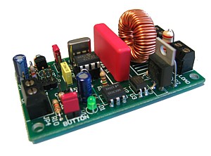
SX13 board dimmer, showed in this article, is a simple and flexible solution to control brightness of a single lamp
or more complex lighting system. Using its four control modes (button, analog voltage, serial RS232 or serial TTL level),
this dimmer fits every need. The chance to place the dimmer inside a DIN rail case, makes it mountable on every ordinary
electric panel.

SX13 board
Introduction
SX13 board, designed and manufactured by Area SX, allows to control the power to supply to an electric load at 220V,
using an external signal. The most common application for this kind of equipments, usually known as dimmer,
is to regulate incandescence lamps brightness.
The external control signal, used to set load power level, may operate in several ways, for example through ordinary
buttons for home light switching or through a variable voltage controlled by a regulator.
In this case, SX13 board has been intended to be very flexible: in fact it is possible to perform the control
through a button, through an analog voltage but also through a PC RS232 serial port.
This feature, together with the chance of connecting up to 32 dimmers on the same serial bus, makes possible
very interesting automatic control realizations. Among these, for example, lighting effects for display windows,
party or show events, interactive atmosphere lighting, day-night cycle simulation for modellism, etc.
General features

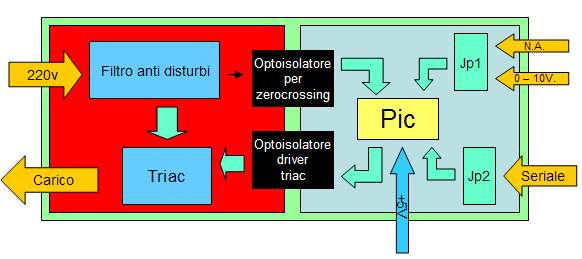
SX13 board blocks diagram
As you can see in the block diagrams, SX13 board is formed by two clearly distinguished sections:
the low voltage section, with 5V power supply, and the high voltage section, directly connected to 220V power supply.
The two sections are electrically divided by optoinsulator: this solution allows to avoid both eventual damage for
control equipments (microprocessor or PC) connected to the board, and also hazardous electric shock for accidentally
touching control signals pins (e.g. with a button) on JP1 connector.
An other important feature of this dimmer is a very effective anti buzz filter, that avoids to spread on the power
network rumours and disturbs.
Low power section is controlled by a PIC12F675 that manages control signals and the effective regulation of the load power.
Power control mode
Four signal control modes are available for dimmer SX13:
- Normally opened switch: this mode is useful for those systems needing human interaction for load power supply.
This button mode control is compliant with serial line control, allowing this way mixed controls.
- Variable analog voltage from 0V to 10V: this kind of interface is the standard of many commercial dimmers,
so connection to existing systems is also available.
- TTL level serial (0-5V): this mode uses just one serial line (only TX) as power control. Using only TX signal
allows to mount the board in a "multidrop" way, in other words sharing the same line with other dimmers.
So it is possible to connect several boards "in series" (so several independently controlled lamps) to realize
completely automatic atmosphere lighting effects. Moreover TTL level signals allow straight connection to any
microcontroller, with no need of adapter.
- RS232 Serial: has the same features of the TTL serial control, but it uses RS232 standard voltage
levels allowing a straight connection to a PC serial port.
Complex systems realization using dimmers series connection

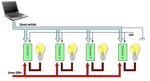
SX13 boards in series
The most interesting interfacing mode is surely the serial one, ideal for SX13 board connection to a microprocessor
(Rabbit, Basicx, PIC) or to a PC.
As already said, serial port uses only the transmission line TX for board control: this allows to connect up to 32
SX13 boards on the same serial line.
Each board may be identified by an address; this address is assigned to the board through the serial line
and it is stored on the PIC Flash memory (so it is not lost when power supply is turned off). When a command for load
power supply control is sent, you need to specify also the destination board address; then the command will be
executed only by the board with that address.
This way it is possible realize group of boards, with the same address, that execute simultaneously the same command.
Moreover a "broadcast" address is available, so to address all the boards: it is useful to send commands
to the whole system under control.
Electric connection
On the board there are several connector for electric connection:
a screw clip for connection to 220V power supply
a screw clip for connection to the electric load
a screw clip for eventual connection to the control button or analg voltage 0-10V
a 5+5 pins male connector where attach power supply voltage (5V) and the TX serial signal.
This connector is compliant with SX01 board (see this article for further description:
Demo board SX01 per Rabbit RCM2200).
In the following picture you can see a 2 SX13 boards system connected to a Serial/USB converter
(see this artiche for further desciption: DLP-USB232M Convertitore USB Seriale) to control the dimmers simply using the PC USB port.

Two dimmers connected to the Serial/USB converter DLP-USB232M
Available versions
The dimmer board is provided by Area SX in two versions: SX13A version, that allows control through button
and serial (TTL and RS232), and SX13B version, that allows control through analog voltage.
The difference between the two versions is simply the firmware of the PIC on board, so it is also possible
to order one more PIC with the other control firmware.
Documentation and examples
Segnala questo articolo:
Tags: - Dimmer - Lampade - Schede Area SX -
|

 Articles
  Hardware
  Expansions
  Multifunctions dimmer

 Articles
  Hardware
  Expansions
  Multifunctions dimmer